Reverse engineering I2C signals: How to decode and analyze data
February 1, 2023
In this post, I’ll delve into the art of reverse engineering hardware signals, using a practical scenario as a case study. While I cannot divulge specific details about the original engagement, the methodology outlined here provides a solid blueprint for anyone interested in signal analysis and hardware reverse engineering. Let’s dive in.
Introduction and Background
Our target scenario involves an alphanumeric control panel where input entered via a keypad is displayed on an LCD screen. While a secure, production-grade system typically avoids routing sensitive, unencrypted data to a peripheral display, vulnerabilities often lie in these assumptions—making it a perfect target for analysis.
The architecture consists of an AVR MCU interfacing with a standard 1602 LCD Module (a 16x2 character display where each character is rendered via a 5x8 pixel matrix). You can reference the module’s user guide here.
Because a standard LCD parallel interface requires a high pin count, this system utilizes an I2C daughterboard to minimize GPIO usage, translating serial data back into parallel commands for the display. Specifically, it relies on the PCF8574T remote 8-bit I/O expander. Its datasheet is available here.
By leveraging I2C, the physical footprint is reduced to just two essential lines: SDA (Serial Data) and SCL (Serial Clock).
Using a logic analyzer and micro IC hook clips, we successfully tapped into the bus and intercepted the I2C traffic.
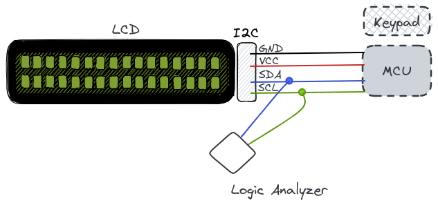
With the raw capture secured, we can proceed to decode the I2C protocol layers and analyze the underlying payload.
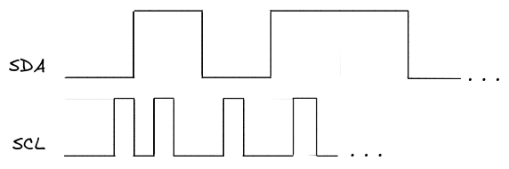
(Note: The image above is a simplified conceptual sketch to protect proprietary data. For actual analysis, assume the captured waveforms are loaded into an open-source tool like sigrok/PulseView or proprietary logic software).
Per the I2C specification, transactions are transmitted in discrete data frames bounded by specific control conditions (START and STOP bits), alongside structural bits like ACK/NACK (Acknowledge/Not Acknowledge) to confirm receipt.
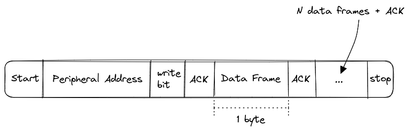
Exporting the decoded hexadecimal stream reveals a sequence of 8-bit values. Instead of controlling raw pixel matrices directly, these bytes represent command structures and character data sent sequentially to the LCD controller. If a hex value results in fewer than 8 bits when converted to binary, it is left-padded with zeros to maintain standard byte alignment:
0xC8=110010000xFD=111111010xF9=01111001
To accurately interpret how these captured bytes map to physical characters, we can audit the target’s underlying library implementation, such as this standard reference: LiquidCrystal_PCF8574.cpp
// write either command or data
void LiquidCrystal_PCF8574::_send(int value, bool isData)
{
  // write high 4 bits
  _sendNibble((value >> 4 & 0x0F), isData);
  // write low 4 bits
  _sendNibble((value & 0x0F), isData);
} // _send()
As illustrated by the driver source code, a single 8-bit payload byte is split into two 4-bit halves, known as nibbles. The upper (most significant) nibble is transmitted first, followed by the lower (least significant) nibble.
This 4-bit split is a hardware constraint: the PCF8574 expander only allocates 4 data lines to the LCD to conserve pins for control lines (like RS and EN). Consequently, splitting the byte into two cycles is actually less efficient for I2C bandwidth, but it is necessary due to the hardware wiring layout.
- To isolate the upper nibble, the byte is bit-shifted right by 4 bits (
>> 4) and masked using a bitwise AND with0x0F. - To isolate the lower nibble, the original byte is directly masked with
0x0Fto clear the upper bits.
Let’s examine the payload execution inside the _sendNibble routine:
// write a nibble / halfByte with handshake
void LiquidCrystal_PCF8574::_sendNibble(int halfByte, bool isData)
{
  _write2Wire(halfByte, isData, true);
  delayMicroseconds(1); // enable pulse must be >450ns
  _write2Wire(halfByte, isData, false);
  delayMicroseconds(37); // commands need > 37us to settle
} // _sendNibble
This method passes the nibble into _write2Wire, which handles the actual physical layer interaction:
void LiquidCrystal_PCF8574::_write2Wire(int halfByte, bool isData, bool enable)
{
  // map the given values to the hardware of the I2C schema
  int i2cData = halfByte << 4;
  if (isData)
    i2cData |= PCF_RS;
  // PCF_RW is never used.
  if (enable)
    i2cData |= PCF_EN;
  if (_backlight > 0)
    i2cData |= PCF_BACKLIGHT;

  Wire.beginTransmission(_i2cAddr);
  Wire.write(i2cData);
  Wire.endTransmission();
} // write2Wire
Inside _write2Wire, the 4-bit nibble is shifted back to the upper half of the transmitted byte (halfByte << 4). The lower 4 bits are then reserved for control flags, which are appended using bitwise OR (|=) operations based on predefined bitmasks:
/// These are Bit-Masks for the special signals and background light
#define PCF_RS 0x01
#define PCF_RW 0x02
#define PCF_EN 0x04
#define PCF_BACKLIGHT 0x08
// the 0xF0 bits are used for 4-bit data to the display.
To extract meaningful text from our traffic dump, we need to isolate the frames containing character data. We do this by filtering for packets where both the Register Select (PCF_RS / 0x01) and Enable (PCF_EN / 0x04) flags are active.
We can validate the state of these flags within our capture by applying a bitwise AND mask to the raw bytes and verifying that the output matches our target flag values.
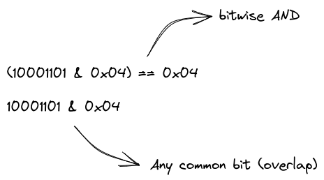
Armed with this understanding of the protocol mapping, we can write a utility script to parse and reassemble our intercepted data frames (assuming the raw I2C log has already been sanitized and saved to a flat text file).
I used JBang to spin up a quick, lightweight Java script. The script parses the hexadecimal dump, filters for frames matching our structural conditions, extracts the payload nibbles, and reassembles them into ASCII characters.
///usr/bin/env jbang "$0" "$@" ; exit $?

import java.util.ArrayList;
import java.util.List;
import java.io.IOException;
import java.nio.file.Files;
import java.nio.file.Path;
import java.nio.file.Paths;
import java.util.stream.Stream;

class i2crev {
    static List<Integer> dataFrames = new ArrayList<>();
    static int RS = 0x01;
    static int EN = 0x04;

    public static void main(String... args) {
       Path path = Paths.get("bytes.txt");
       try(Stream<String> lines = Files.lines(path)) {
         lines.forEach(s -> {
             int value = Integer.decode(s);
             if(((value & RS) != 0) && ((value & EN) != 0)) {
               dataFrames.add(value);
             }
         });
       } catch(IOException e) {
         System.err.println("An error occurred while reading the file: " + e.getMessage());
         e.printStackTrace();
       }

       int size = dataFrames.size() - 1;
       for(int i = 0; i < size; i += 2) {
          int upperNibble = dataFrames.get(i)  & 0xF0;
          int lowerNibble = dataFrames.get(i + 1) >> 4;
          System.out.println(Character.toString((char)(upperNibble | lowerNibble)));
       }
    }
}
By reassembling the nibbles in chronological order, the raw bus traffic is decoded back into the original plain text sent to the display.
This exact logical framework can be adapted across various hardware security workflows—whether you are auditing proprietary I2C peripherals, sniffing SPI flash chips, or reverse engineering custom embedded interfaces.