Reverse engineering I2C signals: How to decode and analyze data
In this post, I’ll delve into the art of reverse engineering signals, using a hypothetical scenario as an example. While I can’t divulge any details about the specific situation, I hope to provide insights that will be useful for those interested in signal analysis and reverse engineering. So, let’s get started!
Introduction and prior knowledge
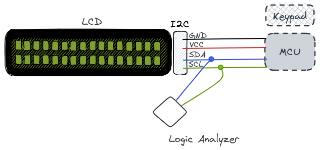
The scenario involves an alphanumeric panel of any type, where the data entered via the keyboard is displayed on an LCD screen. It’s worth noting that a real system wouldn’t transmit sensitive data to an LCD screen, so any resemblance to reality is purely coincidental.
We know that the system consists of an AVR MCU and a 16x2 1062 LCD Module with two rows, each having sixteen characters. A character is formed by a matrix of 5x8 pixels. For more information, we can refer to the user guide here.
Furthermore, due to the high number of pins required to communicate via the LCD parallel interface, the system uses a serial communication via the I2C bus to transform the original parallel communication. Specifically, it uses the PCF8574T, which we can see in the user guide for the 1062 LCD Module, and for which we can find the DataSheet here.
Importantly, the I2C connection requires only two pins: SDA (Serial Data) and SCL (Serial Clock).
We have successfully intercepted the I2C communication using a logic analyzer and a pair of hook clips.
After obtaining the data dump, we can proceed to decode it using I2C protocol and analyze its digital signal.
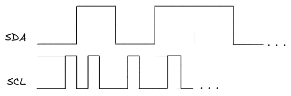
This image is a sketch to avoid revealing the original signal data. It is assumed that at this step, we have the signal loaded into sigrok or similar software.
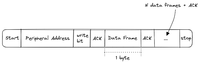
According to the I2C protocol, a message is sent in multiple data frames, with a series of bits for communication control and condition.
By observing the original signal, we can notice that the frames include confirmation of received data (ACK/NACK), start and stop bits, and other control bits.
After exporting the signal in hexadecimal and analyzing the data, we can observe that they are sequences of 8 bits corresponding to the illumination of each character in each column of the LCD panel matrix. Additionally, we can notice that if a number is smaller than 8 bits, it will be padded with zeros on the left to complete the 8-bit sequence.
C8 = 11001000
FD = 11111101
F9 = 01111001
To interpret the captured data, we can analyze the following source code: LiquidCrystal_PCF8574.cpp
// write either command or data
void LiquidCrystal_PCF8574::_send(int value, bool isData)
{
  // write high 4 bits
  _sendNibble((value >> 4 & 0x0F), isData);
  // write low 4 bits
  _sendNibble((value & 0x0F), isData);
} // _send()
As we can see from the source code, the 8 bits (1 byte) of data are sent to the LCD in two nibbles, which are groups of 4 bits. First, the upper nibble is sent, followed by the lower nibble, half a byte at a time.
The first send operation involves a right shift >> of 4 bits, followed by an AND operation with 0x0F.
In the second send, an AND operation with 0x0F is performed.
Performing a right shift of 4 bits and then ANDing with 0x0F in an 8-bit data send process is a common technique for sending data more efficiently.
When the right shift of 4 bits is performed, the 4 most significant bits are shifted out of the value, while the 4 least significant bits remain in place. Then, the AND operation with 0x0F ensures that only the 4 least significant bits are retained, producing a nibble (a 4-bit byte) that can be sent as a smaller data packet.
To send the remaining 4 bits, another AND operation with 0x0F is performed to ensure that only the 4 least significant bits are retained, producing another nibble that can be sent. In the end, the original 8 bits are sent as two 4-bit nibbles each, which is more efficient in terms of bandwidth usage.
Taking a look at the _sendNibble function:
// write a nibble / halfByte with handshake
void LiquidCrystal_PCF8574::_sendNibble(int halfByte, bool isData)
{
  _write2Wire(halfByte, isData, true);
  delayMicroseconds(1); // enable pulse must be >450ns
  _write2Wire(halfByte, isData, false);
  delayMicroseconds(37); // commands need > 37us to settle
} // _sendNibble
It calls the _write2Wire function with the half-byte.
The _write2Wire function is:
void LiquidCrystal_PCF8574::_write2Wire(int halfByte, bool isData, bool enable)
{
  // map the given values to the hardware of the I2C schema
  int i2cData = halfByte << 4;
  if (isData)
    i2cData |= PCF_RS;
  // PCF_RW is never used.
  if (enable)
    i2cData |= PCF_EN;
  if (_backlight > 0)
    i2cData |= PCF_BACKLIGHT;

  Wire.beginTransmission(_i2cAddr);
  Wire.write(i2cData);
  Wire.endTransmission();
} // write2Wire
Here, what it does is left shift by 4 bits and OR with PCF_RS if isData is true, and OR with PCF_EN if enable is true.
We can obtain the values of PCF_RS and PCF_EN from the code:
/// These are Bit-Masks for the special signals and background light
#define PCF_RS 0x01
#define PCF_RW 0x02
#define PCF_EN 0x04
#define PCF_BACKLIGHT 0x08
// the 0xF0 bits are used for 4-bit data to the display.
In the previous image that represents the data frame, we have seen the different frames that make up a message. In our case, we are interested in the data frames of 1 byte. Therefore, the ones that meet the logical condition isData.
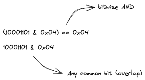
The mask 0x04 enables the display. Thus, the bytes that interest us are those that satisfy both isData and enable conditions.
Since the code performs a bitwise OR operation with the PCF_RS and PCF_EN masks, we can verify if the masks have been applied or not to the value by performing a bitwise AND operation and checking if at least one bit is present in both the value and the mask.
With all this information, we can now write a small application to reverse the captured data frames. We assume that we already have the filtered data frames saved, for example, in a plain text file.
In my case, I’ve used the JBang tool to create a quick script. The script reads in the saved data frames, parses and decodes them using the techniques we’ve discussed, and then reverses the order of the bytes in each frame. Finally, it outputs the reversed data frames to stdout.
///usr/bin/env jbang "$0" "$@" ; exit $?

import java.util.ArrayList;
import java.util.List;
import java.io.IOException;
import java.nio.file.Files;
import java.nio.file.Path;
import java.nio.file.Paths;
import java.util.stream.Stream;

class i2crev {
    static List<Integer> dataFrames = new ArrayList<>();
    static int RS = 0x01;
    static int EN = 0x04;

    public static void main(String... args) {
       Path path = Paths.get("bytes.txt");
       try(Stream<String> lines = Files.lines(path)) {
         lines.forEach(s -> {
             int value = Integer.decode(s);
             if(((value & RS) != 0) && ((value & EN) != 0)) {
               dataFrames.add(value);
             }
         });
       } catch(IOException e) {
         System.err.println("An error occurred while reading the file: " + e.getMessage());
         e.printStackTrace();
       }

       int size = dataFrames.size() - 1;
       for(int i = 0; i < size; i += 2) {
          int upperNibble = dataFrames.get(i)  & 0xF0;
          int lowerNibble = dataFrames.get(i + 1) >> 4;
          System.out.println(Character.toString((char)(upperNibble | lowerNibble)));
       }
    }
}
By reversing the byte order, we can now interpret the data as it was originally intended. This can be useful for analyzing I2C communication protocols or any other protocol that sends data in a specific byte order.
Of course, this is just one example of what we can do with this knowledge. With the right tools and techniques, we can analyze and decode many different types of digital signals.